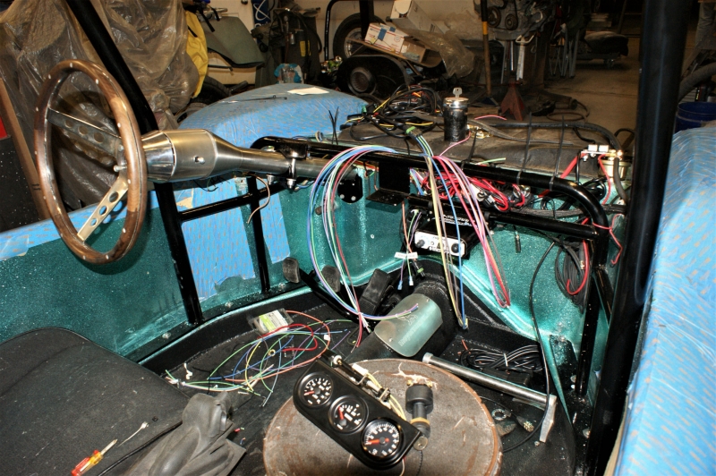
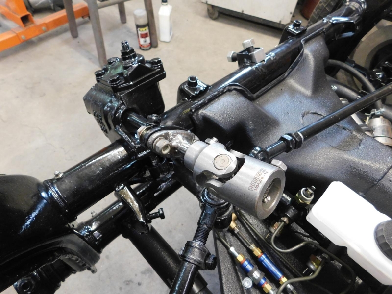
When building your "forever" buggy you look for modifications that will enhance your driving experience well into your retirement years. One of my "wants" on this build was a tilt steering column to ease the ingress and egress for the driver. I decided on a quality-built column from Flaming River (28" column - FR20005-28), plus the steering wheel adapter to accept a Grant style steering wheel (FR3302).
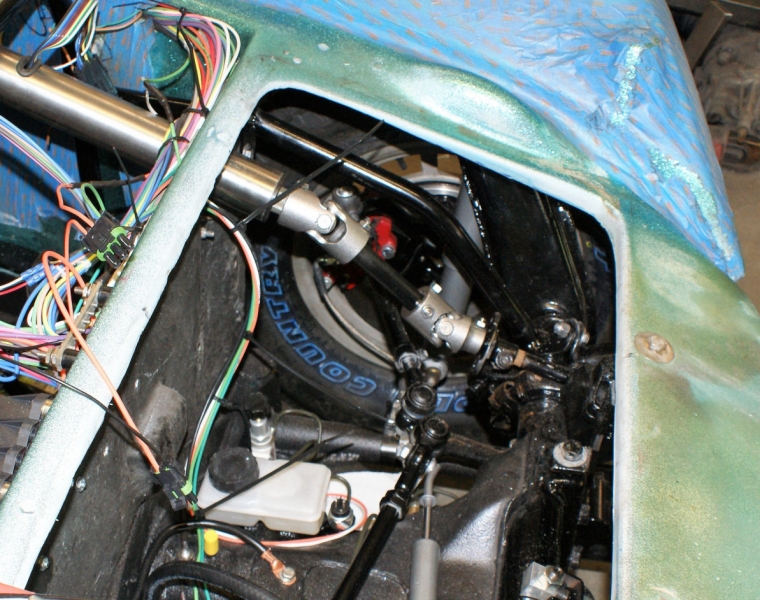
Knowing that we would need U-joints in the mix to get it to mate up with the VW steering box, we went with Borgeson U-joints (115252 & 115218) and Borgeson universal steering shafts (409536).
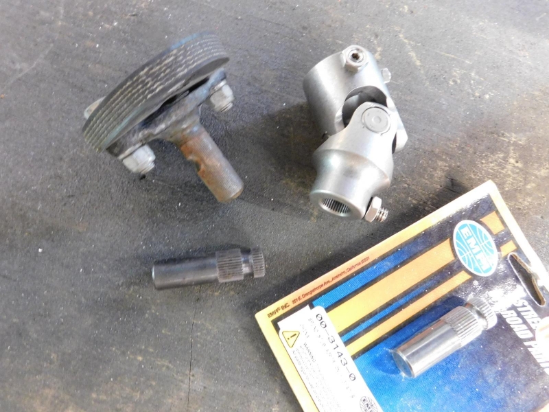
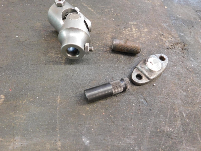
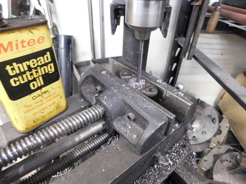
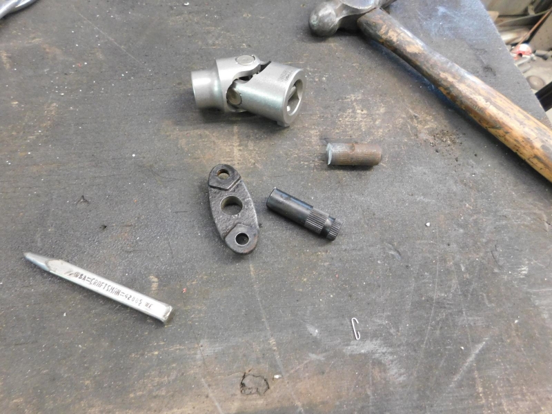
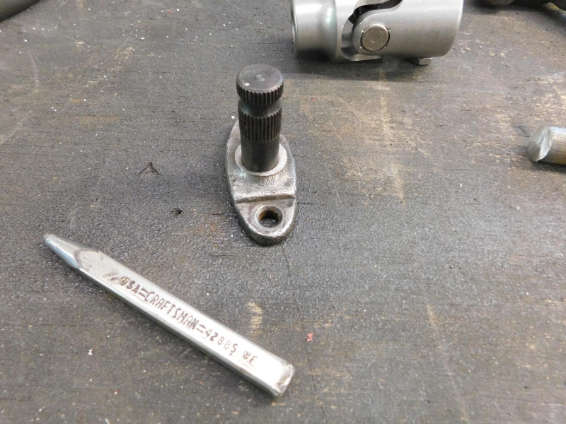
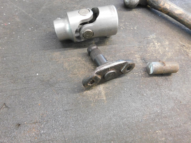
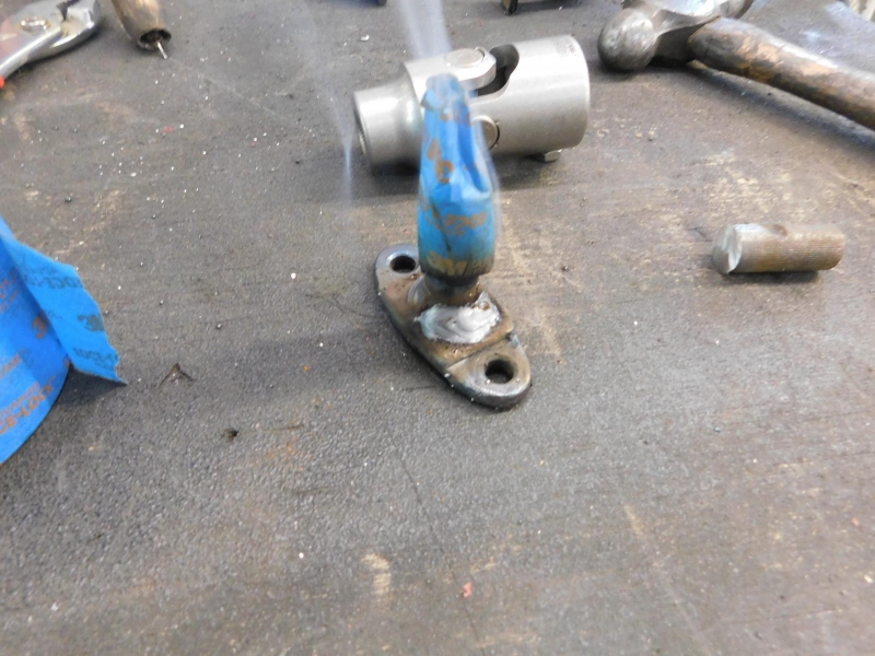
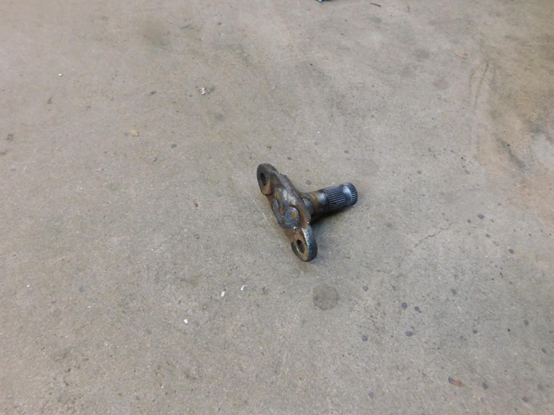
Unfortunately, and somewhat expected, the U-joint's teeth (steering box coupler has 62 splines 16mm and the U-joint has 36 splines 5/8 to 1" DD) didn't match the stock VW steering box coupler/shaft, so another custom mod was required. A steering stub would have to be added to the stock steering box coupler (Empi 00-3143-0).
Watch the Zarkov magic at work:
Finished:
Bud Zeller
Wilmington, NC
Manx Club Member Since 2004 - #2475
Member of the Manx Club's Long Haul League - 2015
2018 NORRA Mexican 1000 - #1356 - Bad News Racing
2022 NORRA Mexican 1000 - #3347 - Bad News Racing & ACME Companies
2023 NORRA Mexican 1000 - #1356 - Bad News Racing
'68 Meyers Manx - M1996F826S
'66 VW Kombi Bus
'73 VW Thing
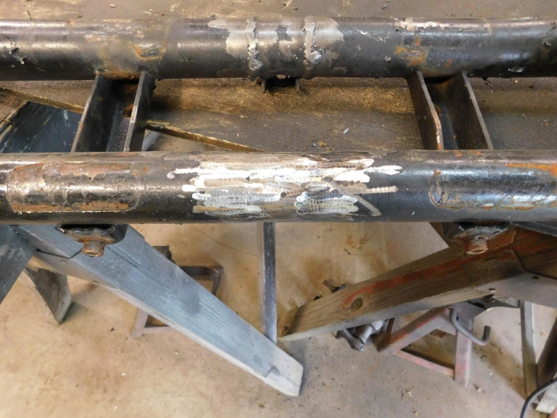
One of the primary reasons for this "Part Deux" restoration was because of the failing of some of the critical components on our buggy. A "known" issue was the front beam and my fear that it would break at the point where the adjusters were welded in. Turns out the beam and the chassis had a few hidden surprises (and not the good kind).
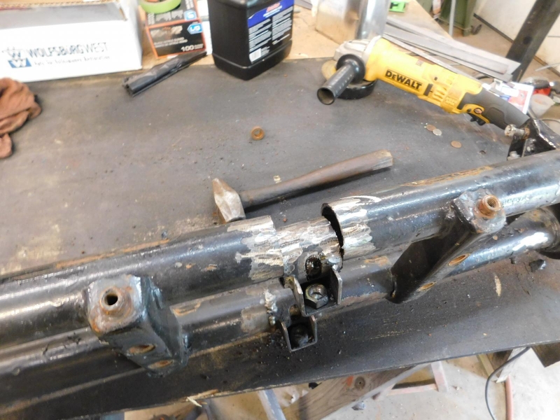
Looking at this image after the adjusters were initially inserted, the naked eye doesn't detect one of the surprises, that the beam is actually bent.
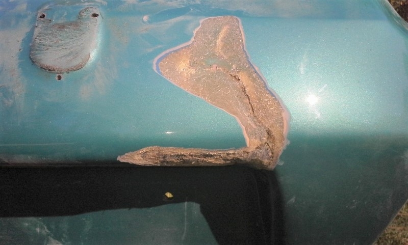
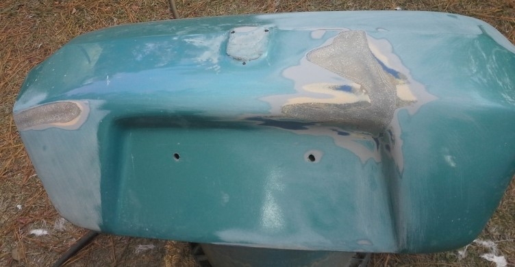
During the "Part Un" (One) restoration in 2014 I found out that hidden under the finish on the hood was evidence that our buggy had some front end damage. In retrospect, this would explain how the front beam was initially bent.
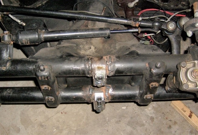
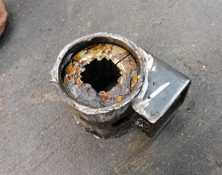
Expecting that we would be able to re-use the original front beam, Dr. Z initiated the adjuster replacements to fix the previous work. Note that there wasn't any penetration with the original welds.
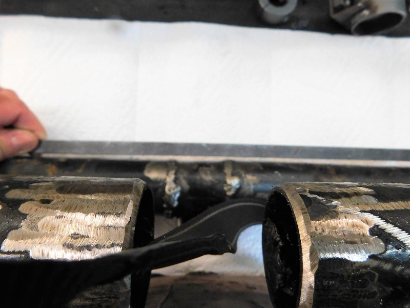
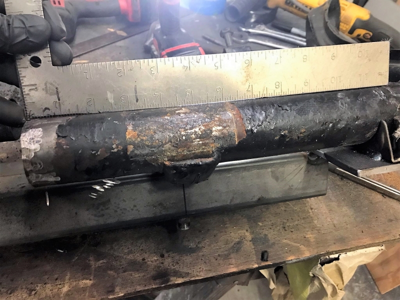
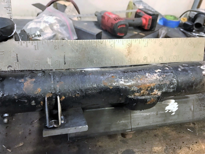
When the beam was placed in the jig for adding the adjusters, it was clear that this beam was toast (see the bend in the beam as compared to a straight edge). A new beam was required.
The second surprise turned out to be that when the original shortening of the chassis was done, it was welded back together "twisted." I don't have a picture of it, but when the chassis was placed on four level jack stands, only three points made contact. This surprise wasn't too bad as the chassis was going to require some adjustment in the overall length, so cutting and re-welding was part of the plan. It is true and level now.
Bud Zeller
Wilmington, NC
Manx Club Member Since 2004 - #2475
Member of the Manx Club's Long Haul League - 2015
2018 NORRA Mexican 1000 - #1356 - Bad News Racing
2022 NORRA Mexican 1000 - #3347 - Bad News Racing & ACME Companies
2023 NORRA Mexican 1000 - #1356 - Bad News Racing
'68 Meyers Manx - M1996F826S
'66 VW Kombi Bus
'73 VW Thing
I've put a lot of individual pictures in this build thread, however the album (link just below) contains a lot more detailed pictures of the during and after process.
Bud Zeller
Wilmington, NC
Manx Club Member Since 2004 - #2475
Member of the Manx Club's Long Haul League - 2015
2018 NORRA Mexican 1000 - #1356 - Bad News Racing
2022 NORRA Mexican 1000 - #3347 - Bad News Racing & ACME Companies
2023 NORRA Mexican 1000 - #1356 - Bad News Racing
'68 Meyers Manx - M1996F826S
'66 VW Kombi Bus
'73 VW Thing
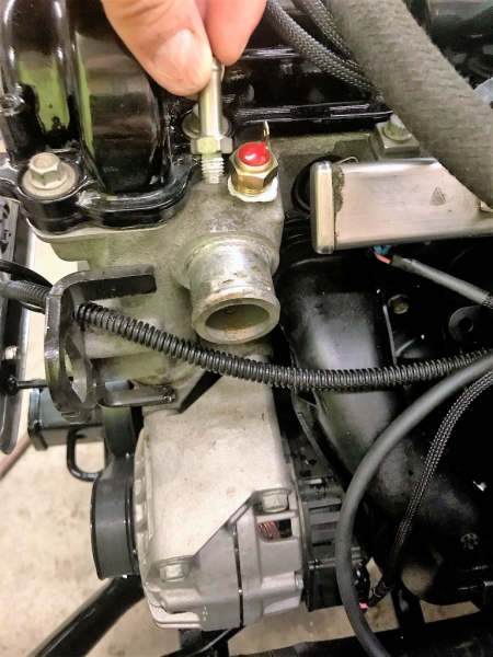
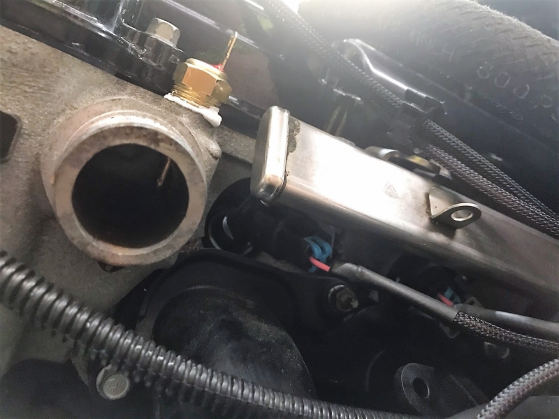
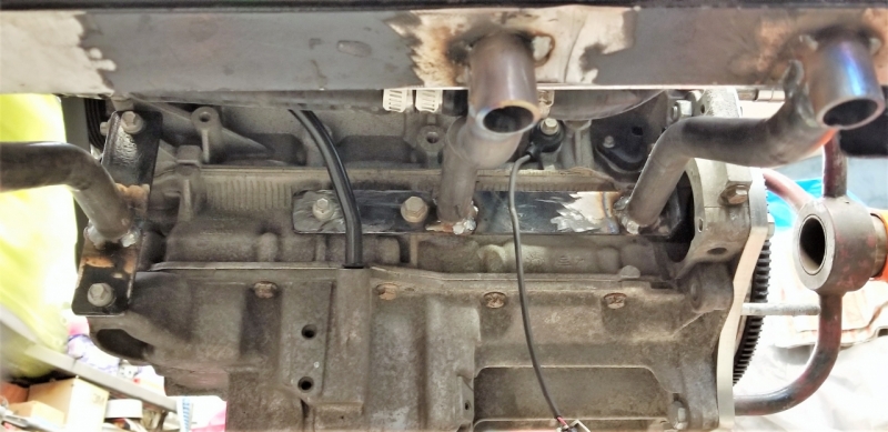
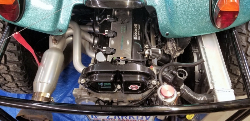
Since this was a Zarkov Industries build, every fine detail was considered right down to the on/off temp switch for the radiator fans. Many are using a toggle switch to turn the fans on/off, or even just wiring the fans up to the switched power off of the ignition. Dr. Z drilled and tapped a Vintage Air Electric Fan Set-point Temp Switch (11205-VUR - Summit Racing) into the outlet port on the head. The harness I have from RDM has a hot lead for powering the fans. The ground line runs to the temp switch and turns the fans on when the H2O temp reaches 205 degrees. The switch turns the fans off when the temp drops to 195 degrees. A relay was wired into the hot lead from a switched wire from the ignition to shut the fans off when the ignition is turned off. Pretty sweet set up.
Bud Zeller
Wilmington, NC
Manx Club Member Since 2004 - #2475
Member of the Manx Club's Long Haul League - 2015
2018 NORRA Mexican 1000 - #1356 - Bad News Racing
2022 NORRA Mexican 1000 - #3347 - Bad News Racing & ACME Companies
2023 NORRA Mexican 1000 - #1356 - Bad News Racing
'68 Meyers Manx - M1996F826S
'66 VW Kombi Bus
'73 VW Thing
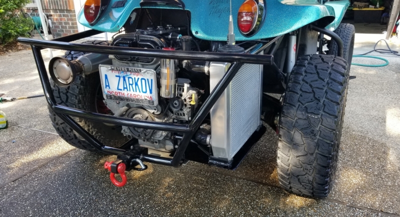
When we started this build I decided that I wanted to try something a little different from the conventional placement of the radiator (aft of the engine) that was tried and proven to keep the Ecotec cool in a fiberglass buggy.
I wanted my radiator parallel to the side of the engine and tucked up under the body as best we could. We found a great custom radiator builder, Chase Bays, that made a small radiator with the capacity to cool a ~400 hp engine that would fit nicely. The overall dimension of the Chase Bays radiator was 11x24x3. So away Dr Z went with fabricating a custom mount that would hold this radiator.
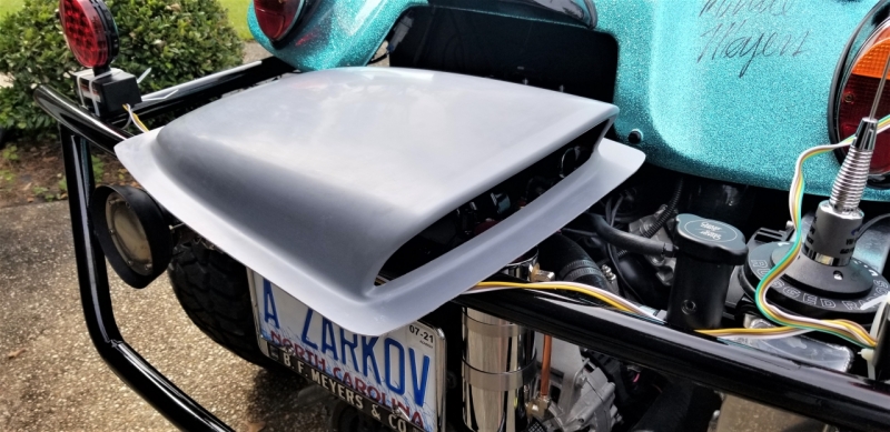
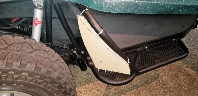
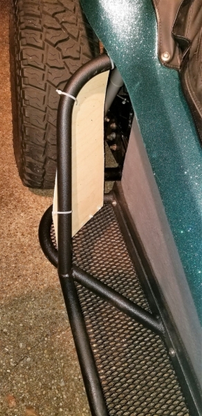
The idea was great, but the cooling was not when traveling at Interstate speeds (70-75 mph). While the Ecotec engine seems to be comfortable in the 205-210 degree range, I was seeing temperatures in the 230-240 degree range. Just too hot (but not over heating). So I purchased and modified an air scoop to fit the Chase Bays radiator in order to capture the air coming down the side of the tub.
What I quickly realized was that there was very little air coming down the side of the tub so I mocked up a diverter board to "force" more air toward the scoop.
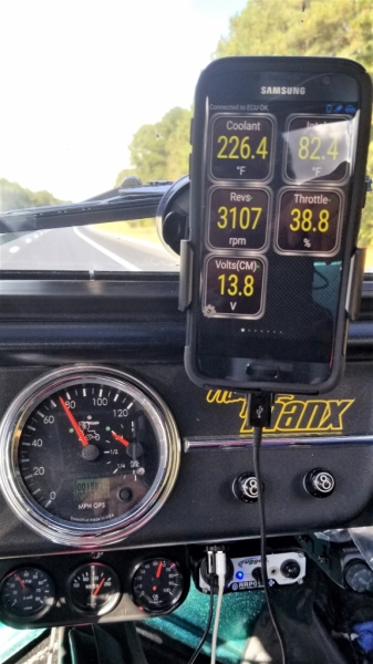
With all these modifications and add-ons, the best I could accomplish, at interstate speed, was cooling the engine to 226 degrees - still too warm especially since I live in a hot southern climate.
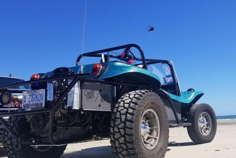
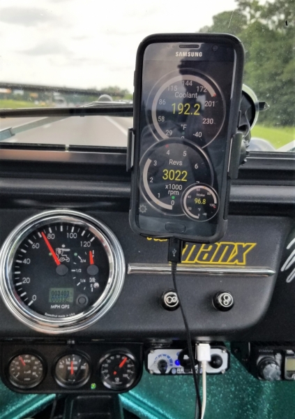
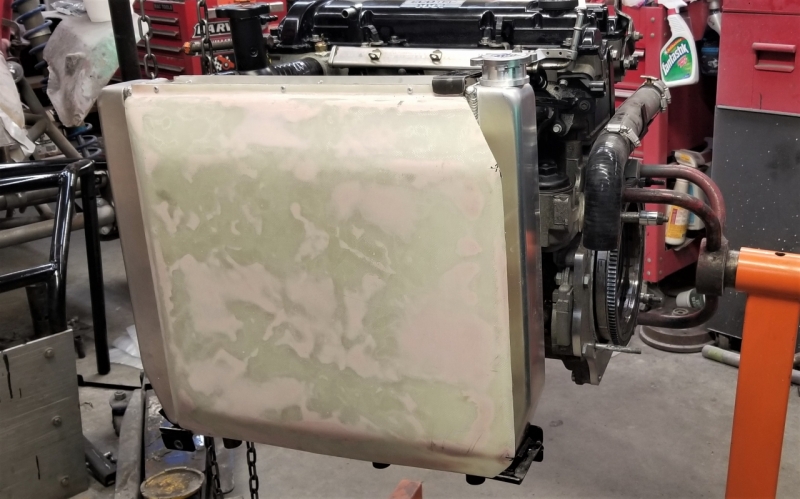
What to do? Throw in the towel and put the radiator on the aft of the engine where I know it'll work? No, I decided to go bigger. I found another really good custom radiator manufacturer in South Carolina called Griffin Radiators. They specialize in after market high horsepower cooling. I ordered their universal radiator (1-58182-XS) with a high capacity SPAL 16 inch fan (with shroud). This radiator is rated at 650 hp. Spoiler alert: combined with a custom air scoop that my wife and I made, problem solved!!! We've just completed a two week, 2600 mile trip, and the highest the engine temperature got (with the outside temp at 90 degrees) was 194 degrees. Most of the time with the outside temps in the low 80s, the engine temp ranged from 171-186 degrees.
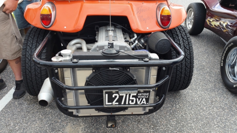
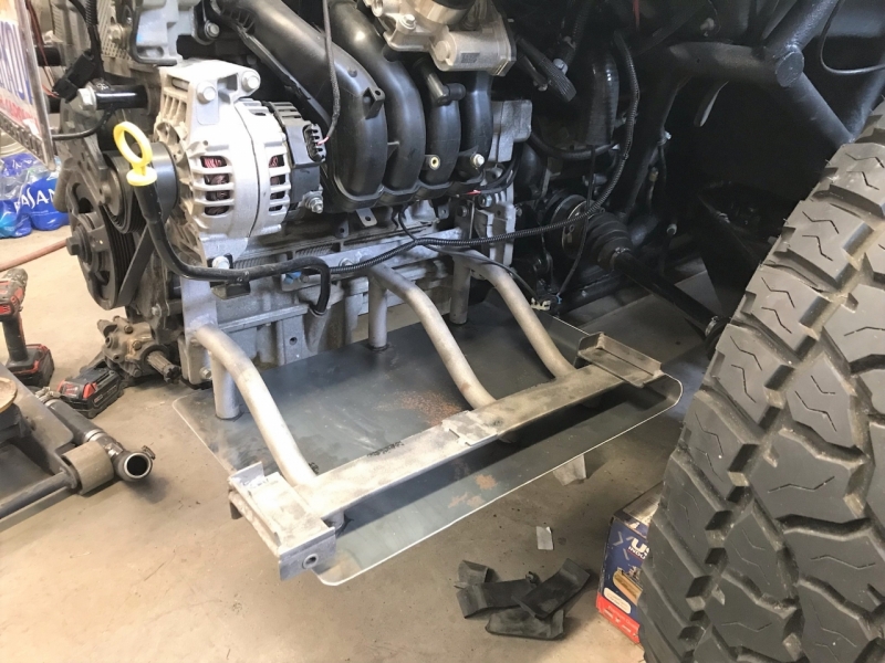
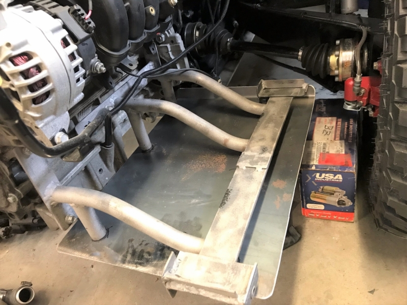
Here are some pictures of the new mounting bracket, with skid plate, that Dr Z had to re-fabricate to hold this larger radiator:
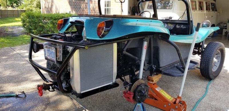
With the radiator mounted:
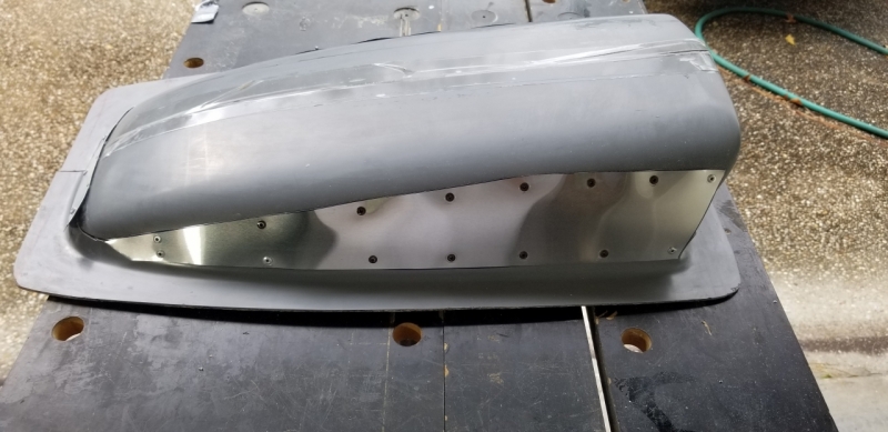
I did a whole thread on making the air scoop from scratch. There are a lot of very detailed pictures on how to make a fiberglass scoop in this thread. If you want to read through that here is the link: https://www.manxclub.com/forum/viewtopi ... =65&t=4547
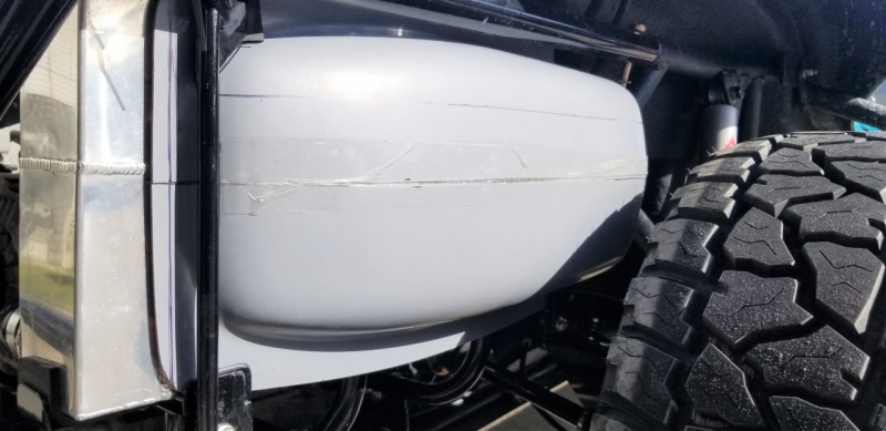
Here is the scoop attached pre-finished and post-finished:
Bud Zeller
Wilmington, NC
Manx Club Member Since 2004 - #2475
Member of the Manx Club's Long Haul League - 2015
2018 NORRA Mexican 1000 - #1356 - Bad News Racing
2022 NORRA Mexican 1000 - #3347 - Bad News Racing & ACME Companies
2023 NORRA Mexican 1000 - #1356 - Bad News Racing
'68 Meyers Manx - M1996F826S
'66 VW Kombi Bus
'73 VW Thing
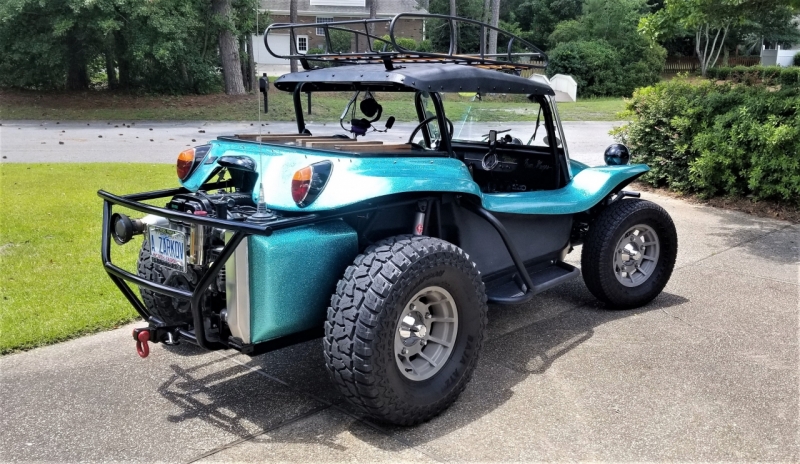
Part of my build included the addition of driving lights to the front bumper. In addition to the aesthetics and appropriateness for a true duel sport buggy, they can be very useful in the right circumstance. After doing a little desert driving I came to realize that amber lenses or lights were probably what I wanted. Unfortunately after settling on the brand and type of lights I wanted, the choices for the amber color were limited. The KC brand of amber lens covers did not excite me, so I did without, until now.
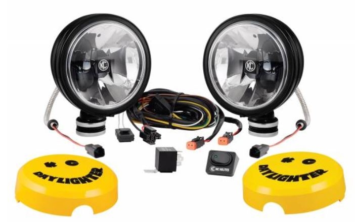
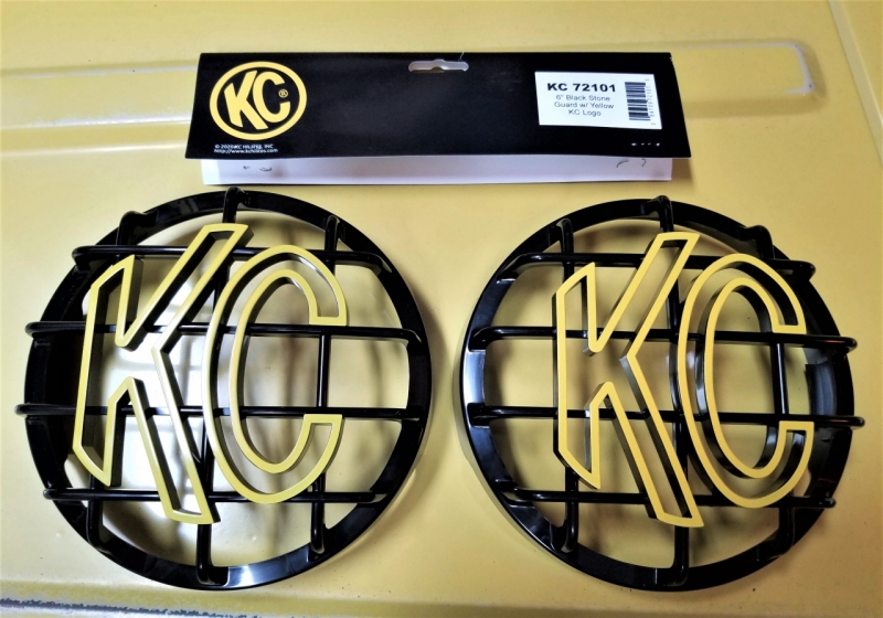
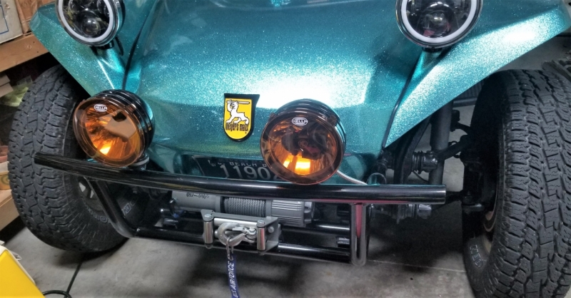
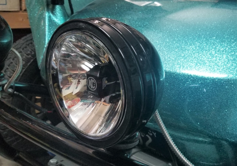
The lights I wanted and had mounted are the KC HiLites 653 Gravity LED Daylighters. In the kit KC provided covers that I absolutely hated. They reminded me of the WalMart smiley price face. So I found and bought the KC 6" Black Stone Guards with the yellow KC logo (they come in other colors).
Here is what comes with the kit:
I trashed the WalMart smiley face light covers and added these:
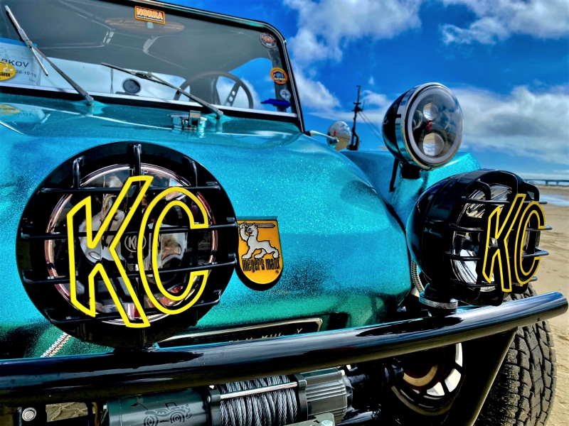
Here is what they look like mounted:
I started searching for amber lens covers and found that KC has amber colored covers available for the light set I bought, however they just weren't my style:
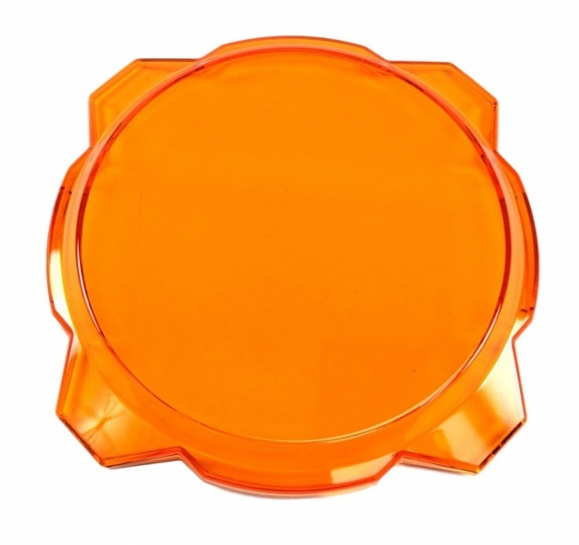
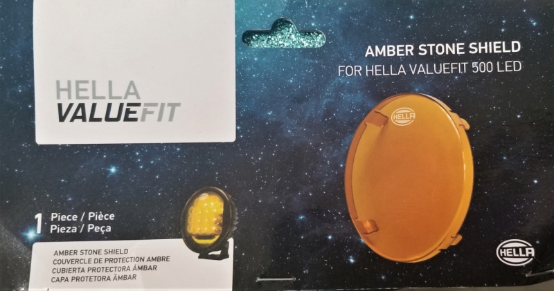
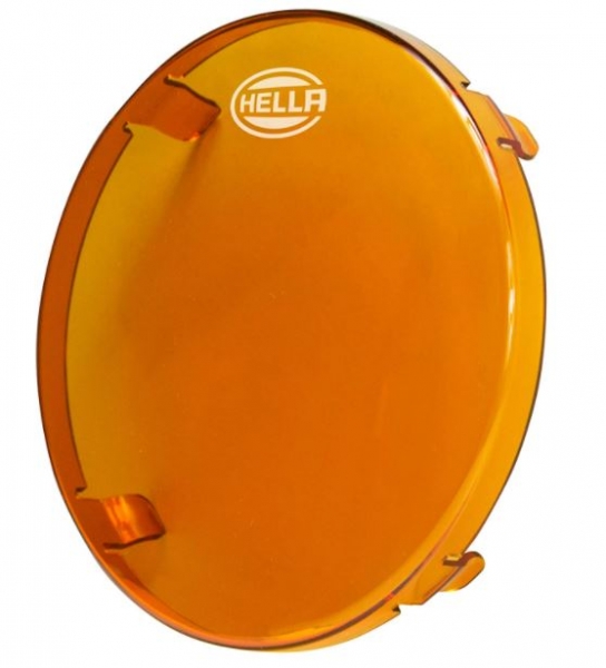
In a random internet search, I found cheap amber lens covers (more to my liking) made by Hella. These covers were meant to snap on and over a Hella brand light, but they also fit the KC lights.
Not too bad, but still not quite what I was looking for. Next the modification.
Bud Zeller
Wilmington, NC
Manx Club Member Since 2004 - #2475
Member of the Manx Club's Long Haul League - 2015
2018 NORRA Mexican 1000 - #1356 - Bad News Racing
2022 NORRA Mexican 1000 - #3347 - Bad News Racing & ACME Companies
2023 NORRA Mexican 1000 - #1356 - Bad News Racing
'68 Meyers Manx - M1996F826S
'66 VW Kombi Bus
'73 VW Thing
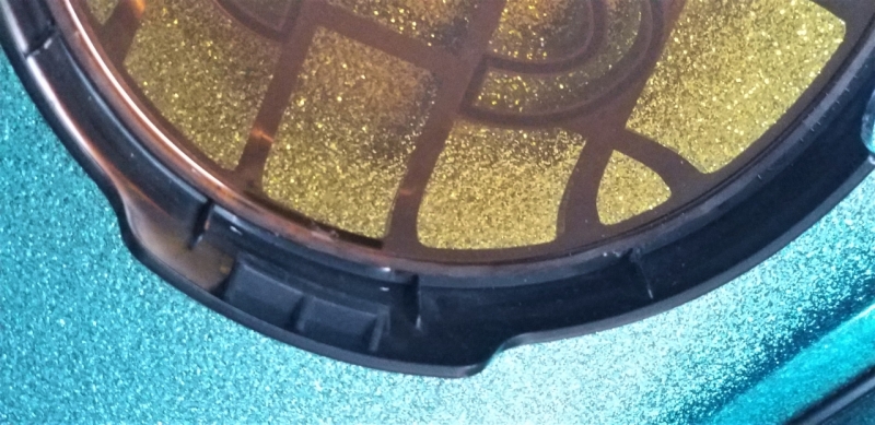
While sitting in the garage and staring at my lights one evening I realized the Hella lenses were almost the same size, in diameter, as the light itself so I tried putting the KC rock guard over top of the Hella lens. I couldn't snap the KC rock guard in place but I realized the Hella lens would fit perfectly inside of the KC rock guards. If I were able to cut the lip off of the Hella lenses, I could put the amber lens inside of the KC rock guards. Since the Hella lenses were not very expensive, I decided to give it a go.
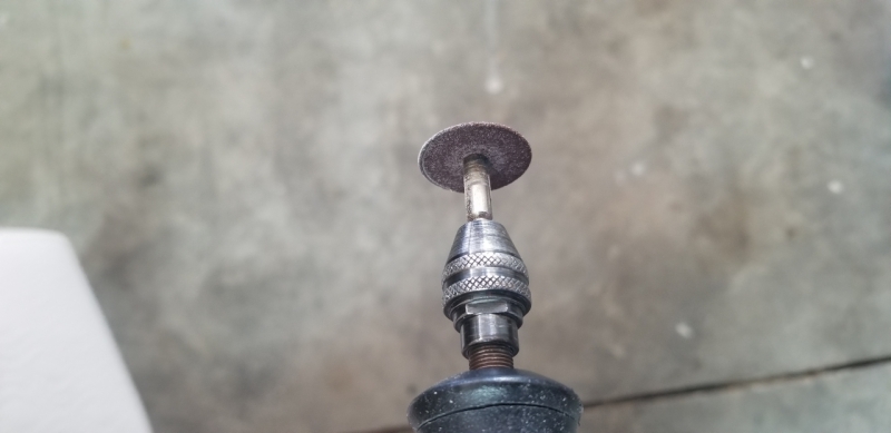
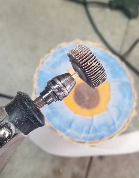
One of the most useful and versatile tools I have is a Dremel. So I put the small cutting blade on and started cutting.
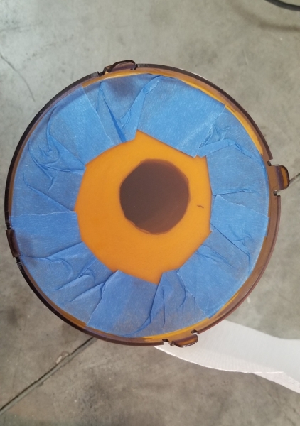
Since I was going to cut from the inside of the lens, I put painter's tape around the flat surface so that the small screw that holds the cutting blade on the Dremel, doesn't scratch up the lens:
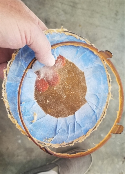
As you would expect, when cutting plastic, the heat from the blade did melt the material but it still cut through nicely:
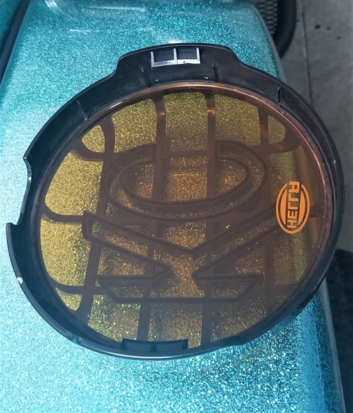
Leaving the painter's tape on protected the lens, I used a paddle-style sanding wheel to knock off the melted edge:
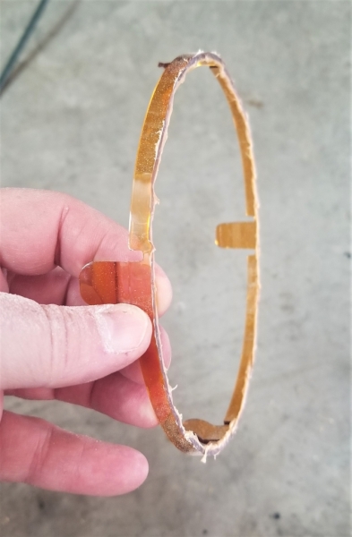
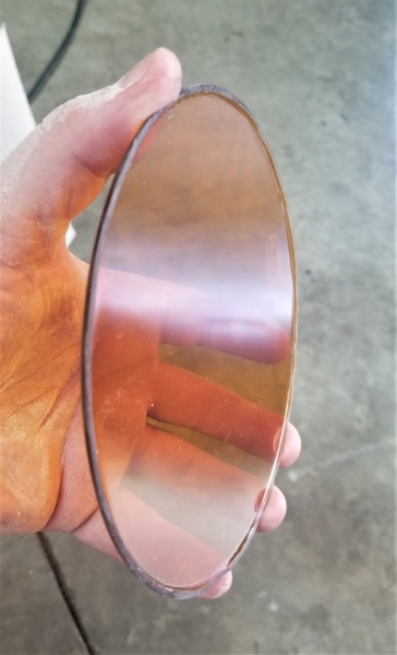
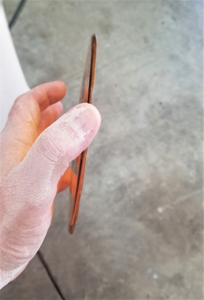
After a little sanding I got the desired result I was looking for:
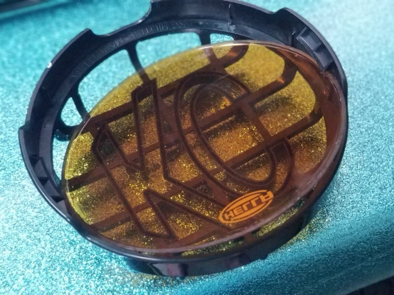
I did have to trim off the little stops inside the KC rock guards to get the lens to fit flush, but it worked perfectly:
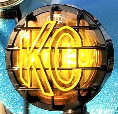
Since the KC light face is perfectly flat, putting the amber lenses between the light and the KC rock guards fit like a glove:
Best part is I have exactly what I wanted and they work pretty well too!
Bud Zeller
Wilmington, NC
Manx Club Member Since 2004 - #2475
Member of the Manx Club's Long Haul League - 2015
2018 NORRA Mexican 1000 - #1356 - Bad News Racing
2022 NORRA Mexican 1000 - #3347 - Bad News Racing & ACME Companies
2023 NORRA Mexican 1000 - #1356 - Bad News Racing
'68 Meyers Manx - M1996F826S
'66 VW Kombi Bus
'73 VW Thing
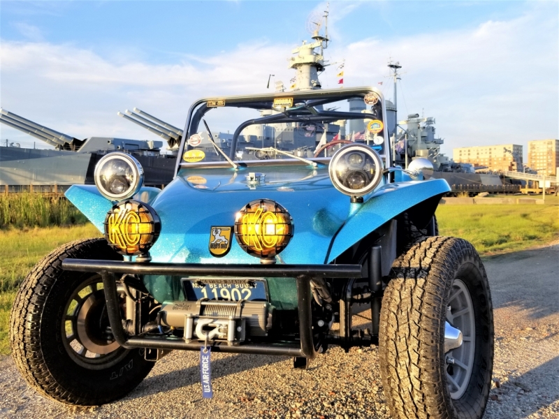
Since I am the President of the "I can't leave well enough alone." Club, I'm always looking at some modification/improvement for our little Fantasy Ship. Last winter's upgrade project was to replace the cable clutch with a hydraulic clutch. Who do you call? Dr. Zarkov, of course.
In his own words, here is Dr. Z's thread on putting the hydraulic clutch into our Zarkov #18:
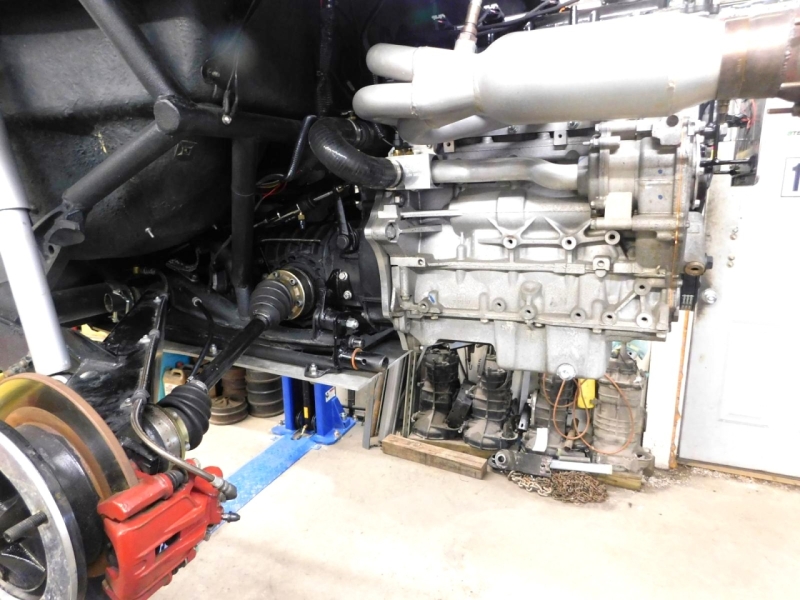
This is one way to install a hydraulic clutch in a buggy. This is a 3 year old build that was built with a 2.4 VVT Ecotec mated to a modified 091 transaxle. The clutch was just updated from a 200 mm to a 9 inch unit with a 3500 pound Stage III Kennedy Pressure Plate.
It takes a pretty good clutch to let the smoke out of 33 inch tall tires, and it results in Clutchites of the left leg. Gets worse as you get older.
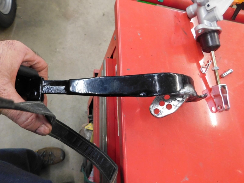
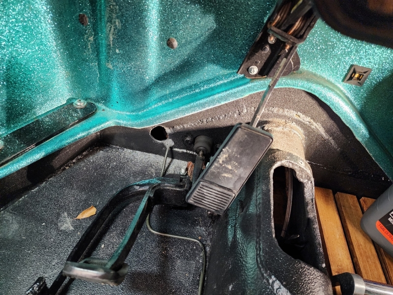
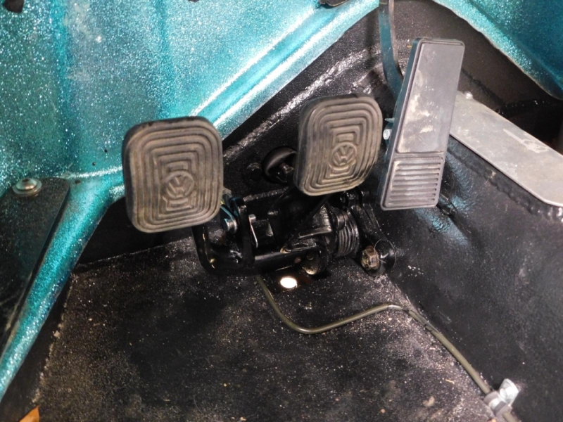
When the buggy was initially built, the late style pedal cluster was used, but I filled in the side of the clutch pedal to make it strong and not flex. So it is a good starting point. I also used the Classic Bug Parts updated pivot shaft that uses the brass bushed end that bolts the clutch cable on, and allows the cable to work smoother than with the stock hook style setup.
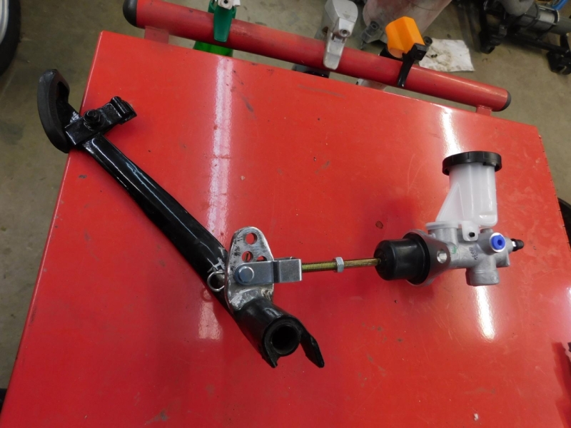
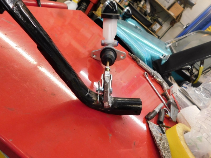
So a mount needed to be welded to the clutch pedal so it could be mated to the clutch master cylinder and press it just like the brake pedal presses into the Brake Master Cylinder.
The extra holes drilled into the mount are to allow the unit to be "tuned" for stroke length and pedal pressure. Each hole is a different distance from the center of the pivot, giving a different radius for a longer/shorter arc length travel.
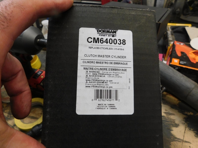
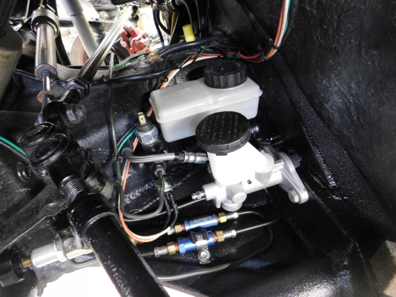
The Master Cylinder is for a Mid 90's Subaru Impreza. It has a 5/8 bore and 1.350" stroke length.
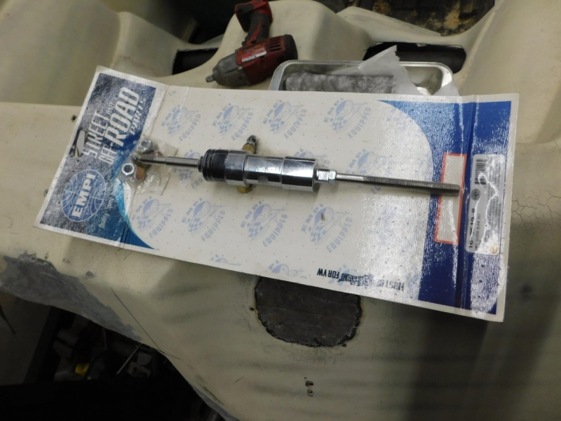
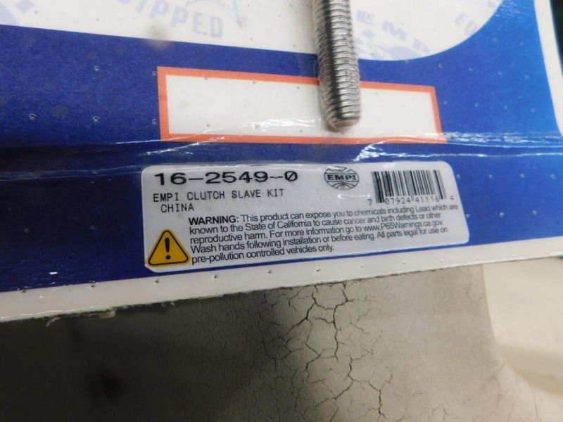
The Slave cylinder is a standard EMPI unit.
The Master comes with a Clevis to hook up easily to a simple mount on the pedal.
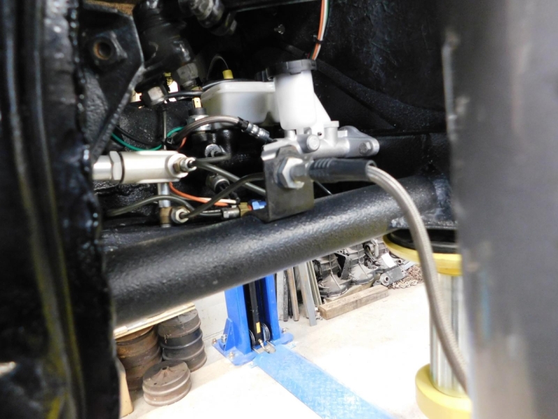
Through some measuring, the Clutch Master Cylinder needs to be mounted at the same level as the Brake Master Cylinder. This is due to the 1.350 clutch master cylinder stroke length. Higher the pedal will bottom out the master and slowly damage it. Lower and it will not move enough fluid to operate the Slave Cylinder.
This was a complex build that included 4 wheel disc brakes that needed residual valves, and a Proportioning valve to take away brakes from the front to keep from lock up conditions or make it respond better in the dirt. So the area is quite busy.
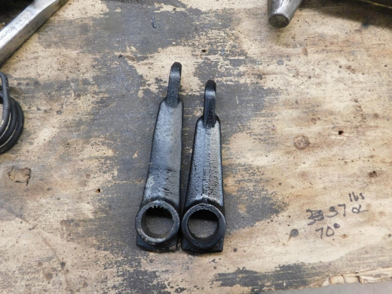
One way to help with pedal pressure is to use the simple lever. By lengthening the clutch actuator arm, it lessens the effort to depress the Pressure Plate diaphragm. During the initial build, I lengthened the arm by 1/2 inch. It does require more pedal movement to perform the same task.
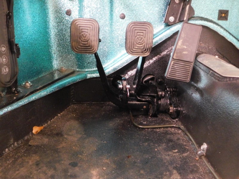
Pedals re-painted and re-installed.
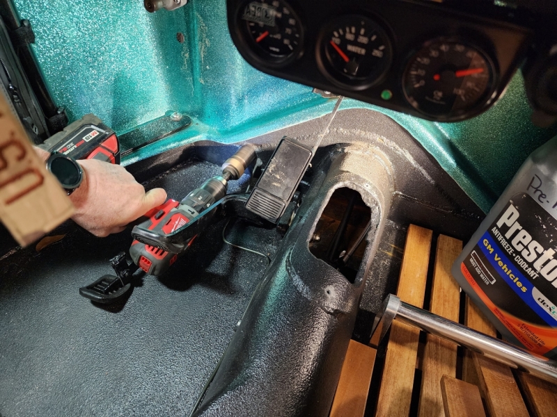
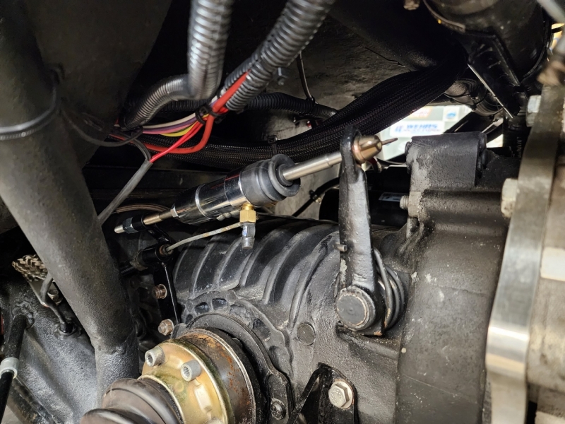
Moving onto the rear. To get the fluid to the rear, I drilled the tunnel and ran the hose through the tunnel exiting out the rear right beside the Boden tube. I went to my local hydraulic shop and had them make me a 96 inch long stainless steel braided and poly coated hose with swaged ends.
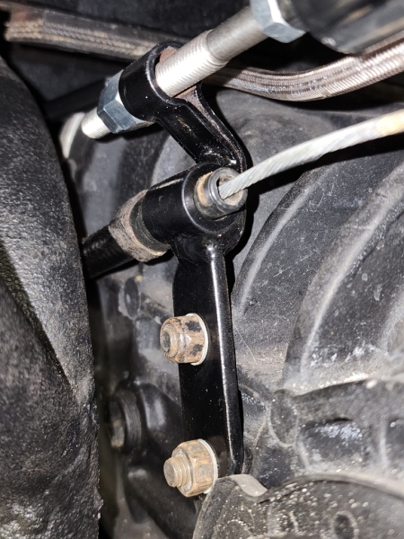
Then at the rear, I set up the Slave cylinder like setting the geometry on engine rockers. I set the slave up so at mid pull of travel, the arm is perpendicular to the slave cylinder. This allows for a even pull that the angle on the slave is the same at rest as it is at full stroke length/pull so no undo force is applied to the slave causing premature wear. This requires a higher fixed end. A simple setup that give a bonus you will see in the photos.
The bonus is the original Boden tube is still in place, as is the original clutch cable. Now the front of the cable is captured by the bolt/bushing so it will not slip off the pedal attachment. This allows for a quick switch over on the trail if the hydraulic system fails. Just return to the cable set up to get home.
Bud Zeller
Wilmington, NC
Manx Club Member Since 2004 - #2475
Member of the Manx Club's Long Haul League - 2015
2018 NORRA Mexican 1000 - #1356 - Bad News Racing
2022 NORRA Mexican 1000 - #3347 - Bad News Racing & ACME Companies
2023 NORRA Mexican 1000 - #1356 - Bad News Racing
'68 Meyers Manx - M1996F826S
'66 VW Kombi Bus
'73 VW Thing